Tuesday, 14 June 2016

Suspension bridge

From Wikipedia, the free encyclopedia
This article is about Suspension bridges with the deck suspended below the main cables. For others, see Suspension bridge types.
Suspension bridge
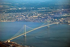
The Akashi Kaikyō Bridge in Japan, world's longest mainspan.
Ancestor Simple suspension bridge
Related Underspanned suspension bridge; see also cable stayed bridge and through arch bridge
Descendant Self-anchored suspension bridge
Carries Pedestrians, bicycles, livestock, automobiles, trucks, light rail
Span range Medium to long
Material Steel rope, multiple steel wire strand cables or forged or cast chain links
Movable No
Design effort medium
Falsework required No
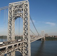
The double-decked George Washington Bridge, connecting New York City to Bergen County, New Jersey, USA, is the world's busiest suspension bridge, carrying 102 million vehicles annually.[1][2]
A suspension bridge is a type of bridge in which the deck (the load-bearing portion) is hung below suspension cables on vertical suspenders. The first modern examples of this type of bridge were built in the early 19th century.[3][4] Simple suspension bridges, which lack vertical suspenders, have a long history in many mountainous parts of the world.
This type of bridge has cables suspended between towers, plus vertical suspender cables that carry the weight of the deck below, upon which traffic crosses. This arrangement allows the deck to be level or to arc upward for additional clearance. Like other suspension bridge types, this type often is constructed without falsework.
The suspension cables must be anchored at each end of the bridge, since any load applied to the bridge is transformed into a tension in these main cables. The main cables continue beyond the pillars to deck-level supports, and further continue to connections with anchors in the ground. The roadway is supported by vertical suspender cables or rods, called hangers. In some circumstances, the towers may sit on a bluff or canyon edge where the road may proceed directly to the main span, otherwise the bridge will usually have two smaller spans, running between either pair of pillars and the highway, which may be supported by suspender cables or may use a truss bridge to make this connection. In the latter case there will be very little arc in the outboard main cables.

Contents

History

The Manhattan Bridge, connecting Manhattan and Brooklyn in New York City, opened in 1909 and is considered to be the forerunner of modern suspension bridges; its design served as the model for many of the long-span suspension bridges around the world.
For bridges where the deck follows the suspenders, see simple suspension bridge.
The earliest suspension bridges were ropes slung across a chasm, with a deck possibly at the same level or hung below the ropes such that the rope had a catenary shape.

Precursor

The Tibetan saint and bridge-builder Thangtong Gyalpo originated the use of iron chains in his version of simple suspension bridges. In 1433, Gyalpo built eight bridges in eastern Bhutan. The last surviving chain-linked bridge of Gyalpo's was the Thangtong Gyalpo Bridge in Duksum en route to Trashi Yangtse, which was finally washed away in 2004.[5] Gyalpo's iron chain bridges did not include a suspended deck bridge which is the standard on all modern suspension bridges today. Instead, both the railing and the walking layer of Gyalpo's bridges used wires. The stress points that carried the screed were reinforced by the iron chains. Before the use of iron chains it is thought that Gyalpo used ropes from twisted willows or yak skins.[6] He may have also used tightly bound cloth.

First

The first design for a bridge resembling the modern suspension bridge is attributed to Croatian polymath Fausto Veranzio, whose 1595 book Machinae Novae included drawings both for a timber and rope suspension bridge, and a hybrid suspension and cable-stayed bridge using iron chains (see gallery below).[7]
The first American iron chain suspension bridge was the Jacob's Creek Bridge (1801) in Westmoreland County, Pennsylvania, designed by inventor James Finley.[8] Finley's bridge was the first to incorporate all of the necessary components of a modern suspension bridge, including a suspended deck which hung by trusses. Finley patented his design in 1808, and published it in the Philadelphia journal, The Port Folio, in 1810.[9]
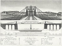
The diagram of the chain bridge over the Menai constructed near Bangor, Wales in 1820
Early British chain bridges included the Dryburgh Abbey Bridge (1817) and 137 m Union Bridge (1820), with spans rapidly increasing to 176 m with the Menai Bridge (1826), "the first important modern suspension bridge".[10] The Clifton Suspension Bridge (designed in 1831, completed in 1864 with a 214 m central span) is one of the longest of the parabolic arc chain type. The current Marlow suspension bridge was designed by William Tierney Clark and was built between 1829 and 1832, replacing a wooden bridge further downstream which collapsed in 1828. It is the only suspension bridge across the non-tidal Thames. The Széchenyi Chain Bridge, spanning the River Danube in Budapest, was also designed by William Clark and it is a larger scale version of Marlow bridge.[11]

Wire-cable

The first wire-cable suspension bridge was the Spider Bridge at Falls of Schuylkill (1816), a modest and temporary footbridge built following the collapse of James Finley's nearby Chain Bridge at Falls of Schuylkill (1808). The footbridge's span was 124 m, although its deck was only 0.45 m wide.
Development of wire-cable suspension bridges dates to the temporary simple suspension bridge at Annonay built by Marc Seguin and his brothers in 1822. It spanned only 18 m.[12] The first permanent wire cable suspension bridge was Guillaume Henri Dufour's Saint Antoine Bridge in Geneva of 1823, with two 40 m spans.[12] The first with cables assembled in mid-air in the modern method was Joseph Chaley's Grand Pont Suspendu in Fribourg, in 1834.[12]
In the United States, the first major wire-cable suspension bridge was the Wire Bridge at Fairmount in Philadelphia, Pennsylvania. Designed by Charles Ellet, Jr. and completed in 1842, it had a span of 109 m. Ellet's Niagara Falls Suspension Bridge (1847–48) was abandoned before completion. It was used as scaffolding for John A. Roebling's double decker railroad and carriage bridge (1855).
The Otto Beit Bridge (1938–39) was the first modern suspension bridge outside the United States built with parallel wire cables.[13]

Structural behavior

Structural analysis

The main forces in a suspension bridge of any type are tension in the cables and compression in the pillars. Since almost all the force on the pillars is vertically downwards and they are also stabilized by the main cables, the pillars can be made quite slender, as on the Severn Bridge, on the Wales-England border.
The slender lines of the Severn Bridge
In a suspended deck bridge, cables suspended via towers hold up the road deck. The weight is transferred by the cables to the towers, which in turn transfer the weight to the ground.
Comparison of a catenary (black dotted curve) and a parabola (red solid curve) with the same span and sag.
Assuming a negligible weight as compared to the weight of the deck and vehicles being supported, the main cables of a suspension bridge will form a parabola (very similar to a catenary, the form the unloaded cables take before the deck is added). One can see the shape from the constant increase of the gradient of the cable with linear (deck) distance, this increase in gradient at each connection with the deck providing a net upward support force. Combined with the relatively simple constraints placed upon the actual deck, this makes the suspension bridge much simpler to design and analyze than a cable-stayed bridge, where the deck is in compression.

Advantages

A suspension bridge can be made out of simple materials such as wood and common wire rope.
  • Longer main spans are achievable than with any other type of bridge
  • Less material may be required than other bridge types, even at spans they can achieve, leading to a reduced construction cost
  • Except for installation of the initial temporary cables, little or no access from below is required during construction, for example allowing a waterway to remain open while the bridge is built above
  • May be better able to withstand earthquake movements than heavier and more rigid bridges
  • Bridge decks can have deck sections replaced in order to widen traffic lanes for larger vehicles or add additions width for separated cycling/pedestrian paths.

Disadvantages

  • Considerable stiffness or aerodynamic profiling may be required to prevent the bridge deck vibrating under high winds
  • The relatively low deck stiffness compared to other (non-suspension) types of bridges makes it more difficult to carry heavy rail traffic where high concentrated live loads occur
  • Some access below may be required during construction, to lift the initial cables or to lift deck units. This access can often be avoided in cable-stayed bridge construction

Variations

Underspanned

Micklewood Bridge as illustrated by Charles Drewry, 1832
Squibb Park Bridge, Brooklyn, built 2013
The Yichang Bridge, a plate deck suspension bridge, over the Yangtze River in China
In an underspanned suspension bridge, the main cables hang entirely below the bridge deck, but are still anchored into the ground in a similar way to the conventional type. Very few bridges of this nature have been built, as the deck is inherently less stable than when suspended below the cables. Examples include the Pont des Bergues of 1834 designed by Guillaume Henri Dufour;[12] James Smith's Micklewood Bridge;[14] and a proposal by Robert Stevenson for a bridge over the River Almond near Edinburgh.[14]
Roebling's Delaware Aqueduct (begun 1847) consists of three sections supported by cables. The timber structure essentially hides the cables; and from a quick view, it is not immediately apparent that it is even a suspension bridge.

Suspension cable types

The main suspension cable in older bridges was often made from chain or linked bars, but modern bridge cables are made from multiple strands of wire. This contributes greater redundancy; a few flawed strands in the hundreds used pose very little threat, whereas a single bad link or eyebar can cause failure of the entire bridge. (The failure of a single eyebar was found to be the cause of the collapse of the Silver Bridge over the Ohio River). Another reason is that as spans increased, engineers were unable to lift larger chains into position, whereas wire strand cables can be largely prepared in mid-air from a temporary walkway.

Deck structure types

Most suspension bridges have open truss structures to support the roadbed, particularly owing to the unfavorable effects of using plate girders, discovered from the Tacoma Narrows Bridge (1940) bridge collapse. Recent[when?] developments in bridge aerodynamics have allowed the re-introduction of plate structures. In the picture of the Yichang Bridge, note the very sharp entry edge and sloping undergirders in the suspension bridge shown. This enables this type of construction to be used without the danger of vortex shedding and consequent aeroelastic effects, such as those that destroyed the original Tacoma Narrows bridge.

Forces

Three kinds of forces operate on any bridge: the dead load, the live load, and the dynamic load. Dead load refers to the weight of the bridge itself. Like any other structure, a bridge has a tendency to collapse simply because of the gravitational forces acting on the materials of which the bridge is made. Live load refers to traffic that moves across the bridge as well as normal environmental factors such as changes in temperature, precipitation, and winds. Dynamic load refers to environmental factors that go beyond normal weather conditions, factors such as sudden gusts of wind and earthquakes. All three factors must be taken into consideration when building a bridge.

Use other than road and rail

Cable-suspended footbridge at Dallas Fort Worth Airport Terminal D
The principles of suspension used on the large scale may also appear in contexts less dramatic than road or rail bridges. Light cable suspension may prove less expensive and seem more elegant for a cycle or footbridge than strong girder supports. An example of this is the Nescio Bridge in the Netherlands.
Where such a bridge spans a gap between two buildings, there is no need to construct special towers, as the buildings can anchor the cables. Cable suspension may also be augmented by the inherent stiffness of a structure that has much in common with a tubular bridge.

Construction sequence (wire strand cable type)

New Little Belt suspension bridge, 1970 Denmark
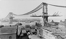
Manhattan Bridge in New York City with deck under construction from the towers outward.
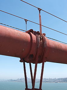
Suspender cables and suspender cable band on the Golden Gate Bridge in San Francisco. Main cable diameter is 36 inches (910 mm), and suspender cable diameter is 3.5 inches (89 mm).
Lions' Gate Bridge with deck under construction from the span's center
Typical suspension bridges are constructed using a sequence generally described as follows. Depending on length and size, construction may take anywhere between a year and a half (construction on the original Tacoma Narrows Bridge took only 19 months) up to as long as a decade (the Akashi-Kaikyō Bridge's construction began in May 1986 and was opened in May, 1998 – a total of twelve years).
  1. Where the towers are founded on underwater piers, caissons are sunk and any soft bottom is excavated for a foundation. If the bedrock is too deep to be exposed by excavation or the sinking of a caisson, pilings are driven to the bedrock or into overlying hard soil, or a large concrete pad to distribute the weight over less resistant soil may be constructed, first preparing the surface with a bed of compacted gravel. (Such a pad footing can also accommodate the movements of an active fault, and this has been implemented on the foundations of the cable-stayed Rio-Antirio bridge. The piers are then extended above water level, where they are capped with pedestal bases for the towers.
  2. Where the towers are founded on dry land, deep foundation excavation or pilings are used.
  3. From the tower foundation, towers of single or multiple columns are erected using high-strength reinforced concrete, stonework, or steel. Concrete is used most frequently in modern suspension bridge construction due to the high cost of steel.
  4. Large devices called saddles, which will carry the main suspension cables, are positioned atop the towers. Typically of cast steel, they can also be manufactured using riveted forms, and are equipped with rollers to allow the main cables to shift under construction and normal loads.
  5. Anchorages are constructed, usually in tandem with the towers, to resist the tension of the cables and form as the main anchor system for the entire structure. These are usually anchored in good quality rock, but may consist of massive reinforced concrete deadweights within an excavation. The anchorage structure will have multiple protruding open eyebolts enclosed within a secure space.
  6. Temporary suspended walkways, called catwalks, are then erected using a set of guide wires hoisted into place via winches positioned atop the towers. These catwalks follow the curve set by bridge designers for the main cables, in a path mathematically described as a catenary arc. Typical catwalks are usually between eight and ten feet wide, and are constructed using wire grate and wood slats.
  7. Gantries are placed upon the catwalks, which will support the main cable spinning reels. Then, cables attached to winches are installed, and in turn, the main cable spinning devices are installed.
  8. High strength wire (typically 4 or 6 gauge galvanized steel wire), is pulled in a loop by pulleys on the traveler, with one end affixed at an anchorage. When the traveler reaches the opposite anchorage the loop is placed over an open anchor eyebar. Along the catwalk, workers also pull the cable wires to their desired tension. This continues until a bundle, called a "cable strand" is completed, and temporarily bundled using stainless steel wire. This process is repeated until the final cable strand is completed. Workers then remove the individual wraps on the cable strands (during the spinning process, the shape of the main cable closely resembles a hexagon), and then the entire cable is then compressed by a traveling hydraulic press into a closely packed cylinder and tightly wrapped with additional wire to form the final circular cross section. The wire used in suspension bridge construction is a galvanized steel wire that has been coated with corrosion inhibitors.
  9. At specific points along the main cable (each being the exact distance horizontally in relation to the next) devices called "cable bands" are installed to carry steel wire ropes called Suspender cables. Each suspender cable is engineered and cut to precise lengths, and are looped over the cable bands. In some bridges, where the towers are close to or on the shore, the suspender cables may be applied only to the central span. Early suspender cables were fitted with zinc jewels and a set of steel washers, which formed the support for the deck. Modern suspender cables carry a shackle-type fitting.
  10. Special lifting hoists attached to the suspenders or from the main cables are used to lift prefabricated sections of bridge deck to the proper level, provided that the local conditions allow the sections to be carried below the bridge by barge or other means. Otherwise, a traveling cantilever derrick may be used to extend the deck one section at a time starting from the towers and working outward. If the addition of the deck structure extends from the towers the finished portions of the deck will pitch upward rather sharply, as there is no downward force in the center of the span. Upon completion of the deck the added load will pull the main cables into an arc mathematically described as a parabola, while the arc of the deck will be as the designer intended – usually a gentle upward arc for added clearance if over a shipping channel, or flat in other cases such as a span over a canyon. Arched suspension spans also give the structure more rigidity and strength.
  11. With completion of the primary structure various details such as lighting, handrails, finish painting and paving are installed or completed.

Longest spans

Suspension bridges are typically ranked by the length of their main span. These are the ten bridges with the longest spans, followed by the length of the span and the year the bridge opened for traffic:
  1. Akashi Kaikyō Bridge (Japan), 1991 m (6532 ft) – 1998
  2. Xihoumen Bridge (China), 1650 m (5413 ft) – 2009
  3. Great Belt Bridge (Denmark), 1624 m (5328 ft) – 1998
  4. izmit Bay Bridge (Turkey),1550 m (5085 ft) - 2016
  5. Yi Sun-sin bridge (South Korea), 1545 m (5069 ft) – 2012
  6. Runyang Bridge (China), 1490 m (4888 ft) – 2005
  7. Fourth Nanjing Yangtze Bridge (China), 1418 m (4652 ft) – 2012
  8. Humber Bridge (England, United Kingdom), 1410 m (4626 ft) – 1981 (longest span from 1981 until 1998)
  9. Jiangyin Suspension Bridge (China), 1385 m (4544 ft) – 1997
  10. Hardanger Bridge (Norway), 1380 m (4528 ft) – 2013
  11. Tsing Ma Bridge (Hong Kong), 1377 m (4518 ft) – 1997 (longest span with both road and metro)
Prince Albert Railroad Bridge over the River Tamar, Cornwall, England, by Isambard Kingdom Brunel.

Bridges


by Chris Woodford. Last updated: March 26, 2016.
Over, under, or straight through the middle? It's a simple-sounding question, but it's challenged every great engineer since ancient times. We like highways and railroads to be straight and level, but Earth's bumps and wiggles make that kind of construction an amazing challenge. How do you take a highway through a valley or make a railroad cross a creek? The simplest answer is to use a bridge. Sounds easy, perhaps, but which type of bridge do you use? Why are there so many different types and how do they all work? Let's take a closer look and find out more!
Photo: One of the world's greatest bridges. Over 150 years after it was completed in 1859, Isambard Kingdom Brunel's amazing Royal Albert Bridge still carries railroad trains 30m (100ft) over the River Tamar, separating Cornwall and Devon in England. But is it a suspension bridge, or is it a truss bridge? Well, it's certainly a truss bridge (notice the thick, tubular, "lenticular" trusses at the top). The vertical ties running from the top curve ("chord") of the trusses, through the bottom curve, down to the deck mean that the bridge does not push outward on its supporting towers, though it does push its loads down onto them. But there are elements of other bridges in here too—bits of suspension bridge, bits of bowstring (tied-arch)—and I think it's a good example of how some bridges are actually hybrids incorporating several different types of bridge in one structure. A modern suspension bridge was built alongside in the 1960s to ferry cars across too (see the photos below).

The wonder of bridges

A Palladian stone arch bridge in Prior Park, Bath, England
In the endless war of people versus nature, there will only ever be one winner—but humans can still console themselves with occasional victories, which is what the world's greatest bridges represent. Whether we need to cross rivers or valleys, connect islands to the mainland, carry cars, people, or manmade waterways, bridges are a brilliant solution whenever nature gets in our way. Historians suppose people invented bridges when they saw how fallen trees could help them cross shallow rivers. Since then, bridges have grown longer, technically more sophisticated, and much more awe-inspiring, slowly evolving from simple stone arches to gracefully swooping suspension bridges several miles long. Buffeted by winds from above, scoured by rivers from below, pounded by traffic all day long, it's a miracle that bridges stay upright as long as they do.
Photo: Bridges do more than simply bear loads: with soaring towers and graceful spans, their inspiring designs are a triumph of architecture as well as engineering. This is the Palladian Bridge at Prior Park, Bath, England, built in 1755, and reputedly one of only four such bridges in the world. You can see that the lower part of the bridge—essentially its deck—rests on five separate stone arches.

How bridges balance forces

Forces make things move, but they also hold them still. It's far from obvious, but when something like a skyscraper looms high above us or a bridge stretches out beneath our feet, hidden forces are hard at work: a bridge goes nowhere because all the forces acting on it are perfectly in balance. Bridge designers, in short, are force balancers.
The biggest and most pervasive force in the universe, gravity, is constantly tugging things down, which isn't such a problem for a skyscraper, because the ground underneath pushes straight back up again. But a bridge spanning a river, valley, sea, or road is quite different: the huge deck (the main horizontal platform of a bridge) has no support directly beneath it. The longer the bridge, the more it weighs, the more it carries, and the bigger the risk it'll collapse. Bridges certainly do fall down from time to time, and quite spectacularly, but most stand happily still for years, decades, or even centuries. They do it by carefully balancing two main kinds of forces called compression (a pushing or squeezing force, acting inward) and tension (a pulling or stretching force, acting outward), channeling the load (the total weight of the bridge and the things it carries) onto abutments (the supports at either side) and piers (one or more supports in the middle). Although there are many kinds of bridges, virtually all of them work by balancing compressive forces in some places with tensile forces elsewhere, so there's no overall force to cause motion and do damage.
Compression and tension forces on six different types of bridges: beam, arch, suspension, cable-stayed, truss, and cantilever

Carrying loads

If a bridge is unloaded, all it really has to do is support its own weight (the dead load), so the tension and compression in its structure are essentially static forces (ones that don't cause movement), changing little from hour to hour or day to day. However, by definition bridges have to carry changing amounts of weight (the live load) from things like railroad trains, cars, or people, which can increase the ordinary tensile or compressive forces quite dramatically. Rail bridges, for example, bend and flex every time a heavy train crosses over them and then "relax" again as soon as the load has passed by.

Environmental forces

Bridges also have to bear ever-changing environmental forces. Arch bridges over rivers, for example, have to cope with water backing up behind them (their abutments often have strategically placed openings to let high flood water drain through). Suspension bridges that carry cars tend to bear the same loads all day long, though, often sited in windy estuaries, they also have to endure squalling gusts of wind, which can set up a twisting force, called torsion, in the bridge deck. (Modern suspension bridges tackle this problem by having decks with aerodynamically designed cross sections, tested in wind tunnels, and may be reinforced with trusses underneath.) Loads that cause a bridge to move back and forth can be particularly dangerous if they make it vibrate wildly at its so-called natural or resonant frequency. Resonance, as this is known, is what makes wine glasses shatter when opera singers get a bit too close; the "singing" of the wind can have equally catastrophic effects on a bridge.
Artwork: Balancing forces in a bridge: Different types of bridges carry loads through the forces of compression ("squeezing"—shown here by red lines) and tension ("stretching"—shown by blue lines): 1) A beam bridge has its beam partly in tension and partly in compression, with the abutments (side pillars) in compression; 2) An arch bridge supports loads through compression; 3) A suspension bridge has its piers (towers) in compression and the deck hangs from thick suspension cables by thinner cables, all of which are in tension. 4) A cable-stayed bridge is similar but the deck hangs directly from the piers from cables. The piers are in compression and the cables are in tension. 5) A truss bridge is a kind of reinforced beam bridge. Like a beam bridge, the top is in compression and the bottom in compression. The diagonal trusses are in tension and the vertical ones are in compression. 6) A cantilever bridge balances tension forces above the bridge deck with compression forces below.

Bridges through history

People find bridges bewitching and bewildering at the same time. Why are there so many different types? How do engineers choose one kind over another? Why have people tended to build different kinds of bridges in different periods of history? There's are easy answers to all these questions—and complex ones too.
One simple answer is that, over thousands of years of human civilization, engineers have gradually developed more sophisticated bridge designs that can span ever greater distances. The oldest bridge types, beams and arches, can only stretch so far before they collapse under their own weight; more sophisticated versions of these designs (truss, box girder, and cantilever bridges) can reach further; and suspension and cable-stayed bridges can go further still. This gradual evolution—and extension—of bridges has been made possible partly by a deeper understanding of engineering, but also by the development of far stronger materials. Arch bridges were popular in the Middle Ages, for example, because they were quick and easy to build from locally sourced materials and lasted a long time with little or no maintenance. When Ironbridge, the world's first cast iron (arch) bridge, was built at Coalbrookdale in Shropshire, England, in 1779, it revolutionized bridge construction; during the 19th century, hundreds of other bridges were built from iron and later steel, including New York City's famous 1883 Brooklyn Bridge, with a span of 486m (1595ft). Suspension and cable-stayed bridges rely on those most dependable of modern materials, reinforced concrete and steel. Some of the newest bridges naturally use the very latest composite materials.

Types of bridges

While it's easy to discuss bridges in this fairly abstract and theoretical way, it's much more interesting to look at some specifics by examining each major type of bridge in turn.

Beam

Beam bridge carrying a railway line
A beam is the simplest (and often cheapest) kind of bridge: a deck, spanning a relatively short distance, held up by a pair of abutments (the vertical supports at either end). Stand on a plank (the deck) stretched between a couple of chairs (the abutments) and you'll make it flex downward in the middle, so it's slightly longer underneath and slightly shorter on top. That tells us that the bottom of a beam is in tension (pulled longer than it would ordinarily be), while the top is in compression (squashed shorter). The load on a bridge like this is transmitted through the beam to the abutments at either end, which are also compressed (squashed downward). The longer the beam, the more likely it is to sag in the middle, which is why basic beam bridges are usually quite short. Modern beam bridges can be much longer, if they're built with box girders (huge hollow boxes made from repeating sections of steel girders and/or reinforced concrete) or braced with trusses (diagonal reinforcements) either on the side or underneath. Beams are explained further in our article on how buildings work.
Photo: A beam bridge carrying a railway line over a road in Dorset, England. Note the abutment on the right-hand side that stops the bridge from collapsing down the hill toward us.

Arch

The Pulteney Bridge in Bath, England is an example of a stone arch bridge.
Arches are the only kinds or bridges supported entirely by forces of compression. There is some tension underneath an arch, but it's usually negligible unless the arch is large and shallow. That makes sense, if you think about it, because an infinitely wide arch would just be a horizontal beam, with its lower side in tension. A bridge deck resting on an arch pushes down on the curve of stones (or metal components) underneath it, squashing them tightly together and effectively making them stronger. The load on a stone arch bridge is transmitted through the central stone (called the keystone), around the curve of other stones, and into the abutments, where the solid ground on either side pushes back upward and inward. Like beam bridges, arches are relatively simple and cheap to construct, and don't need to block a road or river with central piers. They can easily exceed the span of a basic beam, though their big drawback is that they need large abutments, so they're not always an efficient way of bridging something like a highway if a lot of clearance is needed underneath.
Examples of arch bridges include the Mostar Bridge in Bosnia Herzegovina and the Charles Bridge in Prague.
Photo: The Pulteney Bridge in Bath, England is made up of three stone arches. Completed in 1773, it's modeled on the Ponte Vecchio in Florence, Italy.

Truss

Truss bridge over a railway line
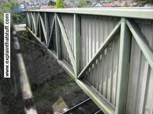
One way to extend the reach of a basic beam bridge is to reinforce it—and engineers have found the best way to do that is with a system of diagonal, triangular bars on the sides, which are called trusses. There are many ways of arranging trusses to support a bridge, giving a variety of intricate and often attractive lattice patterns; lenticular (curved) trusses, used in the Royal Albert Bridge in the top photo, are one example. A typical truss bridge looks like a hollow box with open or closed vertical sides and roof, the sides reinforced with diagonal trusses, and the base resting on girders.
Photo: A truss bridge carrying a pedestrian walkway over a railroad line in Dorset, England.

Cantilever

The Huey P. Long Bridge on the Mississippi River near New Orleans
Two back-to-back beams extending outward from a pier can balance one another—just as a tightrope walker can balance by holding both arms straight out from her body. That's the basic idea behind the cantilever bridge. Normally, when we talk about a cantilever, we mean a beam supported at only one end, like a diving board or see-saw only much more rigid. In a cantilever bridge, there's usually a pair of cantilevers extending from each pier, with a short beam bridge in between, linking them together; alternatively, some have a cantilever extending out from each abutment toward the middle, with a beam bridging them. Cantilever bridges are sometimes hard to recognize because they're typically reinforced with girders and trusses, but easier to spot if you remember that they have multiple sections and often have at least one pier in the middle.
The world's most famous cantilever bridge, the Forth Bridge in Scotland, has three cantilevers (reinforced with a lattice of trusses) with two shorter beam bridges in between them. The world's longest cantilever is the very similar Quebec Bridge, at just under 1km long (987m or 3239ft to be exact). Other examples of cantilever bridges include the Queensboro Bridge in New York City and the Crescent City Connection in New Orleans.
Photo: The Huey P. Long cantilevered bridge on the Mississippi River near New Orleans. Picture courtesy: US Navy.

Suspension

Tamar Road suspension bridge
If you need a bridge that spans even further, a suspension bridge of some kind is really your only option. The genius of a suspension bridge lies in using very tall piers with huge, curving main cables strung between them. Dozens of thinner vertical suspension cables of varying length hang down from the main cables and support the immense weight of the deck and the loads it carries. (And although people always notice the cables in a suspension bridge, they often fail to spot the girders and trusses reinforcing the deck underneath. This is a subtle and quite important point: most bridges are actually composites of two or more of the basic bridge types.) The biggest bridges all use the suspension approach; the world's longest, the Akashi Kaikyō in Japan, is 3.9km (2.4 miles) long.
Famous suspension bridges include the Humber Bridge and the Clifton Suspension Bridge in England, the Golden Gate Bridge in California, and the Brooklyn Bridge in Manhattan, New York City.
Photo: The Tamar Bridge, completed in 1961, spans the River Tamar, the boundary between Cornwall and Devon, England, alongside Brunel's 1859 rail bridge (from which this photo was taken). Notice the truss and girder reinforcements under the deck.

Cable-stayed

Arthur Ravenel Jr. Bridge in Charleston S.C.
A big drawback of suspension bridges is that they need to be anchored to the ground on either side. That's not always possible if there isn't room for the cables or appropriate bedrock to anchor them into. A different kind of suspension bridge, known as a cable-stayed bridge, does away with this by balancing two sets of suspension cables either side of each pier, which supports the load. In a "normal" suspension bridge, the deck hangs from cables of varying length that are themselves supported by the immensely strong main suspension cables. In a cable-stayed bridge, there's only one set of cables that fan out, diagonally, from each pier to the bridge deck, which tends to be stronger and bulkier than in a suspension bridge.
Cable-stayed bridges are significantly shorter than conventional suspension bridges and generally don't span distances much greater than 1km; the world's longest is currently the Russky Bridge in Vladivostok, Russia, at 1.1km (3622ft). Other examples include the Vasco da Gama Bridge in Portugal, the Millau Viaduct in France, the Hangzou Bridge in China, and the Chords Bridge in Jerusalem.
Photo: The Arthur Ravenel, Jr. cable-stayed bridge in Charleston S.C. Picture by Jennifer R. Hudson courtesy of US Navy.

Pontoon

Pontoon bridge in Iraq
Boats obviously float on water, so if you need to build a temporary bridge in a hurry, floating a deck on a series of boats is one possible solution. A bridge like this is called a pontoon—and it's widely used by the military for improvised river crossings (such as when existing bridges have been blown up for strategic reasons). The main problems with pontoon bridges are basic instability and the relatively light loads they can carry.
Photo: A pontoon bridge laid across the Euphrates River in Iraq. Photo by Kevin C. Quihuis, Jr. courtesy of US Marine Corps and Defense Imagery.

Tied arch (bowstring)

Sydney Harbor bridge
Hang a beam bridge from an overhead arch and what you get is a tied-arch bridge. It's a bit like a suspension bridge, because the deck and its load hang from the arch. While the arch supports the deck, the deck also stops the arch from pushing outward, "tying" it in place, so the arch and deck balance one another. That's unlike a conventional arch, where the arch balances by pushing against its abutments. Just as a cable-stayed bridge is more self-supporting than a suspension bridge, because it does away with the anchoring cables, so a tied-arch bridge is more self-supporting than a conventional arch, because it has less need for sturdy abutments. Tied-arch bridges are sometimes called bowstrings because they resemble the arch of a bow pulled out ready to fire an arrow, and because the crossbar ties the bow together in a similar way.
Examples of tied-arch bridges include the Sydney Harbor Bridge in Australia (shown here), the Hell Gate Bridge in New York, and the Tyne Road Bridge in Newcastle, England.
Photo: Sydney Harbor Bridge during the 2000 Olympics. Photo by Robert A. Whitehead courtesy of US Air Force and Defense Imagery.

Lifting and swinging bridges

A US Navy ship sails through the El Ferdan Swing Bridge on the Suez Canal in Egypt
Conventional bridges are impractical if something like a low road has to cross a river or canal through which tall boats need to pass. In that case, we need a mechanical bridge with a deck that can lift up or swing aside whenever necessary. Tower Bridge in London, England is a kind of double drawbridge: it has a split deck that lifts up in the center. There are many examples of swing bridges all over the world. Some have two moving parts that swing to the sides, leaving a central channel clear; others swivel on a central support to open up one or two clean channels of a waterway either side.
Photo: The El Ferdan Swing Bridge carries a railroad line over the Suez Canal in Egypt. Spanning 340m (1100 ft), it's the longest swing bridge in the world. Photo by Daniel Meshel courtesy of US Navy.

How do you design a bridge

Just as bridges balance competing forces from different directions, so engineers have to balance all kinds of considerations when they plan a new bridge.

Type

How far does the bridge need to stretch? That will usually determine the type of bridge that's needed. A very short span (over a small river, road, or rail track) could merit just a low-cost beam or truss; suspension and cable-stayed bridges will generally be unnecessarily complex and expensive; and arched bridges are built much less often than they were in the Middle Ages, partly because other types of bridges use the available space more efficiently. As we've already seen, the type of bridge determines the materials used, to a very large extent. Even so, there may be scope for using local materials so a bridge blends into its environment. That was certainly a feature of traditional arched bridges, often built from local rock or stone. Modern bridges are usually built from steel and concrete and have to rely on design to integrate themselves into their surroundings instead. Box-girder bridges are often manufactured in sections, off-site, which means they can be very rapidly erected. Unfortunately, it also tends to mean that they look very similar and generic.

Crossing

The place where a bridge is being built is also a critically important factor. Is the ground firm enough to take large abutments for an arch? Is there solid bedrock into which suspension cables can be anchored (and, if not, would a cable-stayed bridge be better)? If the bridge has to cross a river, how can piers and towers be safely sunk into its bed so they're not scoured away by the rushing water. The exact location of a bridge is carefully chosen to simplify construction, reduce cost, and ensure the bridge is strong and durable. It's not always possible for bridges to cross in a perfectly straight line, however; bridges sometimes have to cross at an angle (which gives what's known as a skew bridge), curve, or change direction from one section to another. Modern box girder bridges, built from modular deck sections, are easy to curve through even quite dramatic angles.

Load

Apart from the dead and live load, what kinds of occasional, transient forces might the bridge need to withstand? Are there earthquakes or hurricanes and, if so, how can the bridge be designed to survive them? Will a river bridge be able to cope with floods? And what about the loads it will carry? If it's a road bridge, how much is traffic likely to increase over the coming years and decades, and will the bridge always be strong enough to handle them? What if several of these transient forces occur at the same time? For example, suppose a bridge simultaneously has to handle high winds, immense pressure from rising water levels, and heavy traffic?

Other factors

Engineers have to consider all kinds of other factors beside the basic type, location, and strength of a bridge. For example, does a bridge have to carry different types of traffic (a railroad, cars, and pedestrians) and how will it separate them? What about safety considerations (stopping speeding cars from plunging over the edge), and issues like minimizing the risk of suicides (a particular problem for some of the world's tallest bridges)? What kind of maintenance will the bridge need, from regular concrete inspections to systematic painting to protect against corrosion?

Bridges in harmony

Science, technology, and engineering give us confidence we can build stone, iron, steel, or concrete bridges that will survive for many decades. But there's much more to a bridge than merely staying upright as humdrum loads shuttle over it. Think of some of the world's greatest bridges—the Stari Most arch at Mostar, the Brooklyn suspension bridge in Manhattan, the Forth Railway cantilever bridge, or the very recent, cable-stayed Millau Viaduct in France, for example—and you'll quickly realize that great bridges are as breathtakingly memorable as great buildings. Sitting in a river or straddling a valley, you could argue that a bridge disrupts the balance of nature. But bridges connect people and communities together, and many would contest that great bridges are true world wonders that enhance their environment. Who, for example, can imagine San Francisco Bay without the Golden Gate Bridge? So it's maybe just as true to argue that the genius of a great bridge lies in forging a partnership between people and place so that engineering and nature sit happily, side by side.

Why do bridges collapse?

Bridges don't fail very often, but when they do, the results are spectacular and unforgettable. Once you've seen the footage of the Tacoma Narrows bridge resonating in a gale, bucking back and forth before the deck breaks up and crashes to the river below, you'll never forget it. Imagine how terrifying it would have been if you'd been on the bridge at the time!
Bridges always collapse for exactly the same reason: something happens that makes them unable to balance the forces acting on them. A force becomes too great for one of the components in the bridge (maybe something as simple as a single rivet or tie-bar), which immediately fails. That means the load on the bridge suddenly has to be shared by fewer components, so any one of them might also be pushed beyond its limit. Sooner or later, another component fails, then another—and so the bridge collapses in a kind of domino effect of failing materials.
Scene of the I-35 bridge collapse over the Mississippi river in 2007.
Photo: This is the remains of the I-35W Mississippi River bridge, a steel-trussed arch bridge that used to carry a very busy highway over the river. It collapsed unexpectedly in 2007, killing 13 people and injuring 145 more. A report into the disaster found that a metal plate had ripped along a line of rivets, causing a catastrophic failure. Ironically, the bridge was carrying a massive extra load of construction equipment for repairs and reinforcement at the time. Riddled with fatigue cracks and corrosion, it had been deemed "structurally deficient" as far back as 1990. Photo by Joshua Adam courtesy of US Navy.
There are two different ways in which a bridge component can fail catastrophically: weakness and fatigue. First, and simplest, it might be too weak to cope with a sudden transient load. If a bridge is designed to carry no more than 100 cars, but 200 heavy trucks drive onto it instead, that creates a dangerous, transient load. Or if hurricane-force winds buffet the bridge, twisting the deck much more than it's designed to cope with, that can be catastrophic too. So a bridge can fail through weakness because a force exceeds what's called the ultimate tensile strength (the most you can pull) or compressive strength (the most you can push) of the materials from which it's constructed.
But a bridge can also fail even if the forces on it are relatively modest and well within these limits. Everyday materials usually have to undergo repeated stresses and strains—for example, a bridge deck is loaded (when a truck drives across) and then unloaded again immediately afterward, and that can happen hundreds or thousands of times a day, hundreds of days a year. Just as a paperclip snaps when you repeatedly bend it back and forth, the endless cycles of stress and strain, flexing and relaxing, can cause materials to weaken over time through a process known as fatigue. Eventually, something like a metal cable or tie in a bridge will snap even though it's not experiencing a particularly high stress at that moment. Fatigue is often compounded by gradual corrosion (rusting) of metal components or what's informally known as concrete cancer (such as when reinforced concrete cracks after the metal reinforcing bars inside it start to rust).
Engineers try to protect against bridge failures in two main ways. If we learn to see bridges as "living structures," constantly aging and being degraded by weather and the environment. it's easy to understand that they need regular maintenance, just like our homes and bodies. Periodic inspections and preventative maintenance helps us spot problems and correct them before it's too late. Engineers can also protect against bridge failure by building in a factor of safety—designing them so they can cope with forces several times larger than they're ever likely to encounter. That might include extra "redundant" components or reinforcements so that even if one part of the structure fails, others can safely share the load until the bridge can be reinforced or repaired.

Definition of damp proofing


One of the essential requirements of a building is that it should be dry. Dampness in building may occur due to bad design, faulty construction and use of poor quality of materials. Dampness not only affects the life of building adversely, but also creates unhygienic condition for the occupants. The treatment given to prevent leakage of water from roof is generally termed as waterproofing, where as the treatment given to keep the walls, floors and basement dry is termed as damp proofing.


            A damp proof course (DPC) is a physical barrier inserted into the fabric of a building to stop water passing from one place to another. This can be on a horizontal plane, stopping water rising up from the ground by being sucked up by the dry masonry above, or vertically to stop water passing from the outside of a building, though the masonry, to the inside. DPC's have taken many forms through the ages and one of the earliest forms was to use a layer of slate in the construction. Slate is still used but the less expensive plastic version (below right) is now more widely used.
Damp proofing

 Horizontal dpc

Causes of Dampness:
    The dampness in building is a universal problem and the various causes, which are responsible for the entry of dampness in a structure, are as follow.
1)      Rising of moisture from ground
                     The ground on which the building is construction may be made of soil, which easily allows the water to pass. Usually the building material used for the foundations, absorb moisture by capillary action. Thus the dampness finds its way to the floor through the sub structure.
Damp proofing
                                                 Rising of grond water level
2)      Action of rain
                      If the faces of wall, exposed to heavy showers of rain, are not suitable is protected, the become sources of dampness in the structure. Similarly the leaking root also permits the rainwater to enter a structure.
3)      Exposed of top wall
                      The parapet wall and compound wall also should be providing with a damp proof course on the exposed tops. Otherwise the dampness entering thought these exposed tops of such walls may lead to serious result.
4)      Condensation
                       The process of condensation takes place when warm humid air is cooled. This is due to the fact that cool air can contain less invisible water vapour than warm air. The moisture deposits on the walls, floors and ceiling. This is the main causes in badly designed kitchen.
            There are various causes of dampness as mention below
1. If the site located on a site, which cannot be easily drained off, the dampness will be interring in structure.
2. The orientation of a building is also an important factor, the wall obtaining less sunrise and heavy shower of rain are liable to become damp.
3. The new constructed walls remains damp for short duration.
4. Very flat slope of a roof may also lead the penetration of rain water which is temporary store on roof.
5. The dampness also caused due to bad workmanship in construction
Such as defective joints in the roofs, improper connection of wall.
Effect of dampness
The building material such as bricks, timbers, concrete etc, has moisture content, which is not harmful under normal condition. The rise in moisture content of these materials beyond the certain level from where it come visible or when it deterioration leads to the real dampness. If absolute terms, the moisture content of different materials may be same, but the acceptable limit differs from material to material. For instance, the presence of 10 per cent by weight in timber is not harmful. But the same level could saturate a brick or cause deterioration of plaster.
The structure is badly affected by dampness. The prominent effect of dampness is as follow.
1.      A damp building gives rise to breeding of mosquitoes and creates unhealthy condition for those who occupy it.
2.      The metals used in the construction of material are corroded.
3.      The decay of timber takes place rapidly due to dry-rot in a damp atmosphere.
4.      The unsightly patches are formed on the wall surface and ceiling.
5.      The materials used as floor covering are serious damaged.
6.      It results in softening and crumbing of the plaster.
7.      The materials used for wall decoration are damaged and it leads to difficult and costly repairs.
8.      The flooring get loosened because of reduction in the adhesion when moisture enters through the floor.
Methods of damp proofing
Following methods are used for prevent the defect of dampness in structure
1.      Membrane damp-proofing
2.      Integral damp-proofing
3.      Surface treatment
4.      Guniting
5.      Cavity wall construction
1.      Membrane damp-proofing  
                   This consists in proving layer or membrane of water repellent material between the source of dampness and the part of the structure adjacent to it. This type of layer is commonly known as damp-proof course and it may comprise of material like bituminous felts, mastic asphalt, silicon, epoxy, polymers, plastic or polythene sheets, cement concrete etc depending upon the source of dampness, d.p.c may be provided horizontally or vertically in floor, walls etc. provision of d.p.c in basement is normally term as tanking.
DPC
                                   Membrane damp proofing  
General Principles to be observed while laying  d.p.c are as under
1.      The d.p.c should cover full thickness of wall excluding rendering.
2.      The mortar bed upon which the d.p.c is to be laid should be made leveled, even and free projections. Uneven base is likely to cause damage to d.p.c.
3.      When a horizontal d.p.c is to be continued to a vertical face, a cement concrete fillet 75 mm in radius should be provided at the junction, prior to the treatment.
4.      Each d.p.c should be placed in correct relation to other d.p.c, so as to ensure a complete and continuous barrier to the passage of water from floors, walls or roofs.
2. Integral damp proofing
                    This consists in adding certain water-proofing compound with the concrete mix to increase its impermeability. Such compounds are available in market in powdered as well as liquid form. The compounds made from clay, sand or lime help to fill the voids in concrete and make it water proof.
                      Another form of compound like alkaline silicate, aluminum sulphates, calcium chloride etc. react chemically when mixed in concrete to produce water proof concrete.
             Pudlo, permo, impermo etc are some of the many commercially made preparations of water-proofing compound commonly used. The quantity of water proofing compound to be added to cement depends upon the manufacture recommendations. In general, one kg of water proofing compound is added with one bag of cement to render the mortar or concrete water-proofing.
3. Surface treatment
 The moisture finds its way through the pores of material used in finishing. In order to check the entry of the moisture into the pores, they must be filled up. Surface treatment consists in filling up the pores of the surface subjected to dampness. The use of water repellent metallic soaps such as calcium and aluminium oleates and stearates is much effective in protecting the building against the ravage of heavy rain. Bituminous solution, cement coating, transparent coatings, paints and varnishes fall under this category. In addition to other surface treatment given to walls, the one commonly used in lime cement plaster. The walls plastered with cement, lime and sand mixed in proportions of 1:1:6 is found to serve the purpose of preventing dampness in wall due to rain effectively.
DPC
                                           Surface treatment
5.      Guniting
This consists in deposing an impervious layer of rich cement mortar over the surface to be water proofed. The operation is carried out by use of  a machine known as cementgun. The assembly broadly consists of a machine having arrangement for forcing the mixture under pressure through a 50 mm dia flexible hosepipe. The hosepipe has nozzle at its free end to which water is supplied under pressure through a separate connection.
             The surface to be treated is first thoroughly cleaned of dirt, dust, grease or loose particles and wetted properly. Cement and sand usually taken in proportion of 1:3 to 1:4 are then fed into the machine. This mixture finally shot on the prepared surface under a pressure of 2 to 3 kg/cm2 by holding the nozzle of the cement gun at a distance of 75 to 90 cm from the working face. The quantity of water in the mix can be controlled by means of regulating value provided in the water supply hose attachment. Since the material is applied under pressure it ensures dense compaction and better adhesion of the rich cement mortar and hence the treated surface becomes waterproof.
Guniting
Cavity wall construction
                      This consists in shielding the main wall of the building by an outer skin wall leaving a cavity in between the two. The cavity prevents the moisture from traveling from outer to the inner wall.
Cavity wall construction
                           Cavity wall construction